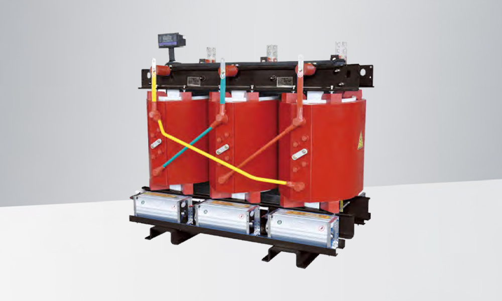
20KV series oil-filled power transformers are more advanced in design, with substantial improvements and enhancements in materials, structure and technology. The high and low voltage clamping parts adopt steel tension band or upper beam and side beam tensioning to form a solid frame structure, which enhances the iron core clamping force and the ability to withstand transportation impact. Strong short-circuit resistance, beautiful appearance and modeling, reliable operation, low loss, low noise, reaching the advanced level of similar foreign products.
| Model No. | Rated capacity (KVA) | Linkage group labeling | Voltage combination (KV) | No-load loss (kW) | Load loss (kW) | No-load current (%) | Short circuit impedance (%) | ||
|---|---|---|---|---|---|---|---|---|---|
| High voltage (KV) | Tap range (%) | Low voltage (KV) | |||||||
| S11-50 | 50 | Dyn11 / Yyn0 | 20 (22) | ±2×2.5 | 0.4 | 0.130 | 1.05 / 1.00 | 1.3 | 6.5 |
| S11-100 | 100 | 0.190 | 1.75 / 1.66 | 1.1 | |||||
| S11-125 | 125 | 0.220 | 2.05 / 1.95 | 1.1 | |||||
| S11-160 | 160 | 0.230 | 2.45 / 2.33 | 1.0 | |||||
| S11-200 | 200 | 0.280 | 2.90 / 2.76 | 1.0 | |||||
| S11-250 | 250 | 0.330 | 3.45 / 3.28 | 0.95 | |||||
| S11-315 | 315 | 0.400 | 4.15 / 3.95 | 0.95 | |||||
| S11-400 | 400 | 0.480 | 5.00 / 4.76 | 0.85 | |||||
| S11-500 | 500 | 0.570 | 6.00 / 5.72 | 0.85 | |||||
| S11-630 | 630 | 0.700 | 6.85 | 0.65 | |||||
| S11-800 | 800 | 0.830 | 8.20 | 0.65 | |||||
| S11-1000 | 1000 | 0.980 | 10.0 | 0.65 | |||||
| S11-1250 | 1250 | 1.19 | 12.1 | 0.60 | |||||
| S11-1600 | 1600 | 1.44 | 14.5 | 0.60 | |||||
| S11-2000 | 2000 | 1.70 | 17.2 | 0.55 | |||||
| S11-2500 | 2500 | 2.01 | 20.3 | 0.55 | |||||
Note 1: For transformers with rated capacity of 500KV·A and below, the load loss values above the diagonal line in the table are applicable to Dyn11 coupling group, and the load loss values below the diagonal line are applicable to Yyn0 coupling group.
Note 2: When the annual average load ratio of the transformer is between 30% and 36%, the highest operating efficiency can be obtained by adopting the loss values in the table.